Department of Mechanical Engineering
College of Engineering, Guindy
Anna University, Chennai
Department of Mechanical Engineering
Anna University

| Working surface table | 750 x 250 mm |
| Maximum job height admitted between table and new grinding wheel | 275 mm |
| Self-acting longitudinal traverse of the table | 800 mm |
| Cross table traverse hydraulic | 285 mm |
| Table traverse speed range per minute | 1.5 to 1.8 m |
| Automatic cross feed range per stroke at each reversal | 0.5 to 10 mm |
| Size of grinding wheel (dia x width x bore) | 250 x 25 x 76 mm |
| Speed of the wheel | 2400 rpm |
| Model | TMT-600 |
| Center Height | 127 mm |
| Max. Grinding length | 600 mm |
| Work Speed 6 Steps | 40 to 320 rpm |
| Work Swivel | 90° |
| Swivel of wheel head | 45 x 45° |
| Internal Grinding with standard adapter | 80 x 25 mm |
| Wheel Motor | 3 Hp |
| Work head motor | 0.5 Hp |
| Hydraulic pump Motor | 0.1 Hp |
| Internal Grinding attachment motor | 1 Hp |
| Hydraulic feed range | 50 to 1000 mm/min |
| Max. Table swivel | 9+3 deg |
| Grinding wheel diameter | 355 x 40 x 127 mm |
| Grinding wheel speed | 1600, 2000 rpm |
| Model | GMT 75 |
| Grinding Diameter | 2-75 mm |
| Grinding Wheel Size | 350 x 127 x 100 mm |
| Control Wheel Size | 225 x 76 x 100 mm |
| Grinding Wheel Speed | 1850 rpm |
| Control Wheel Speed | 20-100 rpm |
| Grinding Wheel Motor | 5 HP / 1400 rpm |
| Control Wheel Motor | 1.5 HP / 1440 rpm |
| Coolent Pump | 0.10 HP |
| Size | 1600 x 1350 x 1425 mm |
| Model | M2U |
| Machine No | 5060 |
| Code No | M2/273 |
| Table Size | 1300 x 1300 mm |
| Speed Range | 68 to 1270 rpm |
| Precision machine vice without SB width of jaws | 160 mm |
| Universal dividing head with tailstock centre steady and train of gear | 130 mm |
| Circular table motorised | φ400 mm |
| Milling arbour | φ40 x 27 x 500 mm |
| Spindle Motor | 3 HP |
| Cross Travel Y | 395 mm |
| Model | 4E |
| Longitudinal Travel X Manual | 890 mm |
| Table Size | 127 x 254 x 82 mm |
| Quick Travel | 127mm |
| Type | RM 60 |
| Speed Range | 50-2100 rpm |
| Cutting Feed | 0.05 to 1.25 m/min |
| Machine Dimension (Length x width) | 1800 x 800 mm |
| Read spindle speed against cutting tool diameter | 4 to 100 mm |
| Model | 6M 12K |
| Table Rotating | 360° |
| Table Size | φ400 mm |
| X - Axis | 0 - 4 mm / 1 Rev - 6 mm |
| Y - Axis | 0 - 120 mm / 1 Rev - 4 mm |
| Z - Axis | 0 - 30 mm / 1 Rev - 1.35 mm |
| Maximum diameter for straight and skew toothed spur wheels for high capacity | 125 mm |
| Maximum diameter for straight and skew toothed spur wheels for standard capacity | 250 mm |
| Maximum Milling Width for spur wheels | 125 mm |
| Minimum number for teeth to be cut | 6 |
| Maximum module pitch for high capacity | 1.5 |
| Maximum module pitch for Standard capacity | 2.5 |
| Diameter of work table | 150 mm |
| Metal Thickness | 1 to 6 mm |
| Over all Height | 1600 mm (Approx) |
| Wire Diameter | 6 to 10 mm |
| Spur Gear | EN 353 RC 55 to 60 |
| Worm Gearbox | 40:1 |
| Flange Mounting Motor | 3 Phase 440 v |
| Speed | 1400 rpm |
| Solid Roller Rod Length | 300 mm, EN 8 |
| Roller Machine Finishing | 65 Hrc with CG |
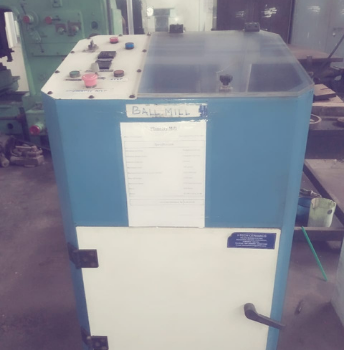
| Grinding Jan (Vial) | Tungsten Carbide |
| Grinding Media (Balls) | Tungsten Carbide |
| Volume of the Jar | 250 ml |
| Maximum Load | 100 grams |
| Machine Dimension (Length x Width) | 510 x 680 mm |
| Over all height | 1100 mm |
| Maximum Speed | 300 rpm (Variable) |
| Drive | Belt Drive |
| Motor | 0.5 HP/230 v/50 Hz |
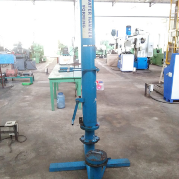
| Max.Energy for Forming | 3500 Nm |
| Overall Length | 1100 mm (Approx) |
| width | 1100 mm (Approx) |
| Height | 2200 mm (Approx) |
| Spillage of water during impact | No |
| Die | Suitable for above |
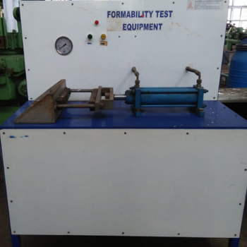
| Material to be tested in ductile sheet metal Max. | Width 20 mm |
| Test Length | 200 mm Approx |
| Loading by hydraulic cylinder with load indication maximum load | 50 KN |
| Over all length | 1210 mm |
| Height | 1400 Approx |
| Width | 540 mm |
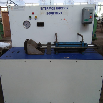
| Maximum drawing force by hydraulic cylinder | 50 KN |
| Overall length | 1210 mm |
| Width | 540 mm |
| Height | 1400 Approx |
Swing Over bed ≥ 500 mm
Swing Over Cross slide ≥ 250 mm
Swing in Gap Diameter ≥ 700 mm
Distance Between Centers ≥ 1000 mm
Height of centres≥ 200 mm
Valid Length of Gap ≥ 250 mm
Width of bed ≥ 400 mm
HEADSTOCK
Spindle nose – A2-5 or A2-6 – (Any other standard used to be specified)
Spindle bore 40 - 55 mm
Taper bore in Spindle–Preferred size - Metric 45-60 mm (Any other size to be specified)
Taper bore in spindle sleeve - MT3 / MT4 / MT5
Range of spindle speed (forward and reverse) - 50- 3000 rpmwith options for more than16 steps – variable speed drive.
Width of bed ≥ 400 mm
TOOL SLIDE
Compound rest travel ≥ 250 mm
Cross slide travel ≥150 mm
Swivel range of cross slide ± 450 or better
Graduation in apron hand wheel – 0.2 mm or better
Graduation on cross slide – 0.005 mm or better
Graduation on compound slide – 0.01 mm or better
Max. section of tool 25 x 25mm
Lead screw thread 6mm - 12 mm
Longitudinal feeds range 0.04-1.4 mm/rev or better with at least 16 steps
Cross feeds range 0.02-0.7 mm/rev or better with at least 16 steps
TAILSTOCK
Stock of quill ≥ 80 mm
Spindle travel ≥ 150 mm
Taper bore in spindle sleeve - MT3 / MT4 / MT5
Hand wheel graduation – 0.05 mm or better

| Motor | 3 Phase, 220 V delta connection,1hp motor 1400 rpm |
| Rpm Indicator | Yes |
| Max Speed | 400 rpm |
| Ball Size | 6 to 8mm |
| Number of vial | 4 Nos |
| Material of vial | Stainless Steel |
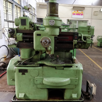
| Max. Workpieces length | Outer Gear:500 mmInner Gear:600 mm |
| Max.Processing modulus | 8 mm |
| Gear Width | 100 |
| The moving distance from axis of cutter to worktable | 0 to 340 mm |
| The cutter holder to worktable distance | 50-225 mm |
| The dia. of worktable | 380 mm |
| The dia. of spindle | 80 mm |
| The stroke | (times/minutes) |
| Grades | 6bands (55,110,172,252,344,504) |
| The cutter circle feeding | φ of cutter 100mm |
| 8 Bands | 0.1, 0.12, 0.16, 0.20, 0.28, 0.36, 0.46, 0.56 mm/Storke |
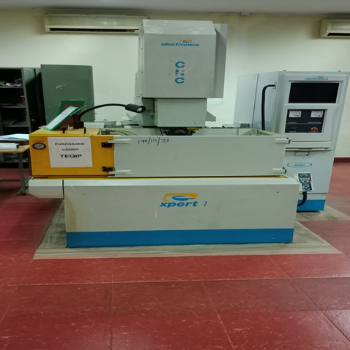
X x Y x Z : 400 x 300 x 300 mm
Work Tank : 900 x 600 x 350mm
Electrode discharge dressing
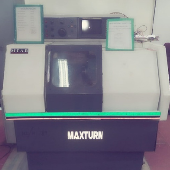
| Swing over bed | : 380mm |
| Max. turning dia | : 200mm |
| Max. turned length | : 250mm |
| X-axis travel | : 250mm |
| System resolution | : .001mm |
| Mechanical resolution | : .01mm |
| Power Chuck | : 160mm dia |
| Spindle motor | : FANUC AC 3.75/5.5kw 50/60Hz 3PH 415 V 14 A |
| Machine / Motor Make | Creative Automation/ABB |
| Motor Type | 15 KW, 3-phase Induction motor, 1440 rpm, 415V&50Hz |
| Spindle Drive | Through direct coupling |
| Spindle Standard | ISO 40 standard with manual tool clamping |
| Spindle Speed | 100 to 2500 rpm (infinitely variable) |
| The Tool Head Tilt Angle | 5° on either side |
| Separate AC Servo motor for each axis Feed rate programmable | 1 to 2000 mm/min |
| Rapid Traverse for Z axis | 2000 mm/min |
| Rapid Traverse for X and Y axis | 1800 mm/min |
| Incremental Feed | 0.001 mm |
| Electronic hand wheel input resolution | 0.1 / 0.01 / 0.001 mm |
| Traverse Range X /Y / Z Axis | 720 / 300 / 350 mm |
| Maximum Load X /Y / Z Axis | 25 / 25 / 30 KN |
| Schneider Motion Controller Lexium 058 | 2D Contouring Control, Central touch screen for display of all position and current machine Condition, Linear & Circular interpolation etc |
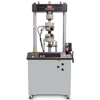
| Make | Instron |
| Model | 8801 |
| Dynamic Load Capacity | ±100 kN / ±22 kip |
| Actuator Stroke | 150 mm / 5.9 in |
| No. of Columns | 2 |
| Frame Stiffness | 390 kN/mm |
| Maximum weight | 625 kg / 1377 lb |
| Configuration | Twin-Column High-Stiffness Load Frame with Actuator in Lower Table |
| Lifts and Locks | Hydraulically-Powered Lifts and Locks |
| Load Cell | Patented1 Dynacell™ Fatigue-Rated Load Cell Mounted to Upper Crosshead with Capacity to Suit Actuator |
| Load Weighing Accuracy | ±0.002% of Load Cell Capacity or 0.5% of Indicated Load, Whichever is Greater –Down to 1/250th of Full Scale |
| Hydraulic Pressure Supply (Required) | 207 bar / 3000 psi |
| Electrical Supply | Single-Phase Mains 90-132 or 180-264 VAC 45/65 Hz Power Consumption: 800VA max |
| Operating Environment | +10 to +38°C (+50 to +100°F) with 10 to 90% Humidity Non-Condensing |
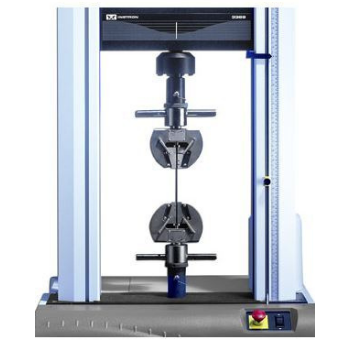
| Make | Instron |
| Model | 3369 |
| Force Measurement Accuracy | ±0.5% of reading down to 1/200 of load Cell capacity. ±1% of reding from 1/200 to1/500 of the load cell capacity |
| Displacement Measurement Accuracy | ±0.02mm or 0.15% displacement (whichever is greater) |
| Strain Measurement Accuracy | Meets or surpasses the following standards: ASTM E83, ISO 9513, and EN 10002-4. |
| Testing Speed Accuracy | (Zero or constant load) ±0.2% of set speed |
| Data Acquisition Rate at the PC | Up to 0.5 kHz simultaneous on force, displacement, and strain channels |
| Force Capacity | 50 kN / 11250 Ibf |
| Vertical / Horizontal Test Space | 1193 / 420 mm, 47 / 16.5 in |
| Testing Speed Range Min-Max (Return) | 0.005 to 500 (500) mm/min0.0002 to 20 (20) in/min |
| Position Control | 63 nm / 2.5 µin |
| Resolution | |
| Frame Axial Stiffness | 82 kN/mm, 468200 lb/in |
| Maximum Force at Full Speed | 25 kN / 5625 Ibs |
| Maximum Speed at Full Force | 250 mm/min, 10 in/min |
| Max specimen thickness/Width | 12.7mm / 25mm |
| Footprint Dimensions (h × w × d) | 158 × 76 × 71 cm62 × 30 × 28 in |
| Weight | 141Kg / 312 Ibs |
| Maximum Power Requirement | 700 VA |
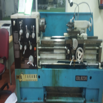
| Center Height | 175 mm |
| Admit Between Center | 650 mm |
| Swing over Bed | 350 mm |
| Swing over Cross Slide | 215 mm |
| Bed Width | 240 mm |
| Spindle Nose / Bore / Taper | Camlock / 41 mm / MT-5 |
| Spindle Speed / Range | 8 / 54-1200 rpm |
| Motor | 3 hp |
| Power | 415 V, 3 Ph, 50 Cycles |
| Lead Screw | Dia. 28 mm / pitch 6 mm |
| Threads Metric | 0.5 - 6 mmBritish 4-60TPI |
| Feeds | 32/0.0489-0.716mm/rev.Cross32/0.5x Longitudinal |
| Feeds / Long Cross | Dia. 50 mm - Travel 140mm / MT-3 Taper MT-3 |
| Model | MV |
| Speed | 1430 rpm |
| Motor | 4hp |
| Frame Size | B 204L |
| Cutting capacity | 60 mm |
| Cut-off wheel diameter | 10 inch |
| Spindle | 2800 rpm |
| Motor | 3 hp 3 phase |
| Machine (Length x width) | 700 x 650 mm |
| Over all Height | 1400 (Approx) |
| Cooling System two jets with recirculation coolant tank | 50 L |
| Cam Vise | 1 No |
| T Slot Plate | 1 No |
| Coolant pump capacity | 1/3 HP |
Work Table Size : Max Length 600mm, Width 350mm
Tilting the tool: 0 to 3 degrees
Spindle Speed : 800 – 2000 rpm
Spindle Motor : 11kW/ 440V
Spindle Bore : ISO 40
Tool Holder : To matched with Spindle Bore (ISO 40)
Lubrication : Centralized Lubrication System (Manually)
Tool Recommended: Max shank Diameter = 25mm
PLC : SIMENS / FATEK
| Make / Model | 0Yuken / Four Column 290 |
| Construction | Heavy Pillar Rods and Plates |
| Piller Ref Diameter | 95mm (4 Nos) |
| Maximum Pressure Capacity | 1000 kN |
| Maximum Reverse Force | 250 kN |
| Day Light Gap | 1000 mm |
| Pressing Cylinder Stroke / Bore / Ram | 800 mm / 250 mm / 200 mm |
| Top Ram Table Size | 600 x 600 x 75 mm (M16-T Slot) |
| Bottom Table Size | 600 x 600 x 90 mm (M16-T Slot) |
| Cushion Bed Size | φ320 mm |
| Cushioning cylinder capacity | 250 kN |
| Cushioning Stroke /Bore / Ram | 150 / 125 / 100 mm |
| Cylinder Seals | Imported Seals (Halite Make) |
| Maximum working pressure | 20 N/mm2 |
| Gauge | Analog Pressure Gauge (Glycerin Filled) |
| Pressure Sensor | Electronic Type (Kellar Make) |
| Oil Tank Capacity | 400 litres |
| Motor | 15 HP, 3 Phase, 1440 RPM,(Crompton Greaves) |
| Pump | High Flow - Gear Pump |
| Pressure Control Valve | Knob Type (Polyhydron/Yuken Make) |
| Directional Control Valves | Solenoid Valves (Yuken Make) |
| Pressing Cylinder Speed | Approach : 50-55 mm/secPressing : 8 – 10 mm/sec Return: 140 – 150 mm/sec |
| Cushion Cylinder Speed | Upward : 35-38 mm/sec Downward:90-100mm/sec |
| Load Cell | 1500 kN capacity with 0.1 Kn least count |